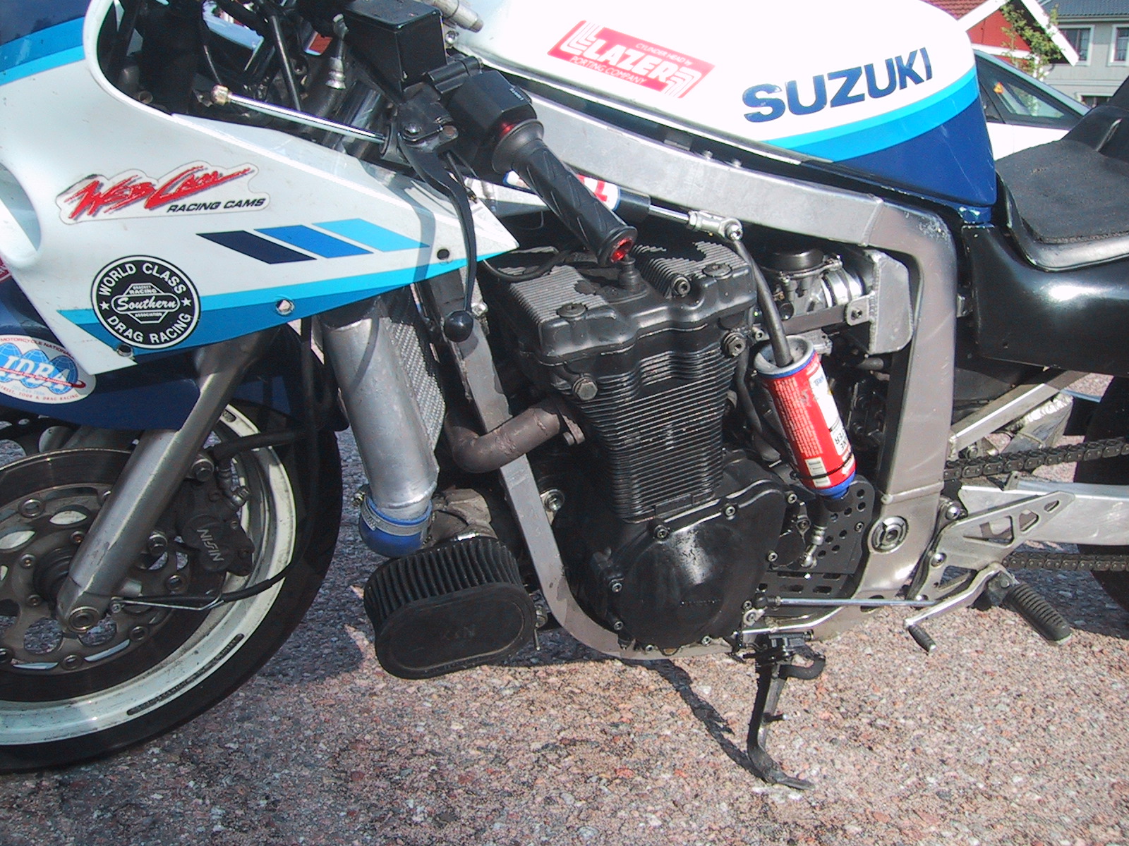
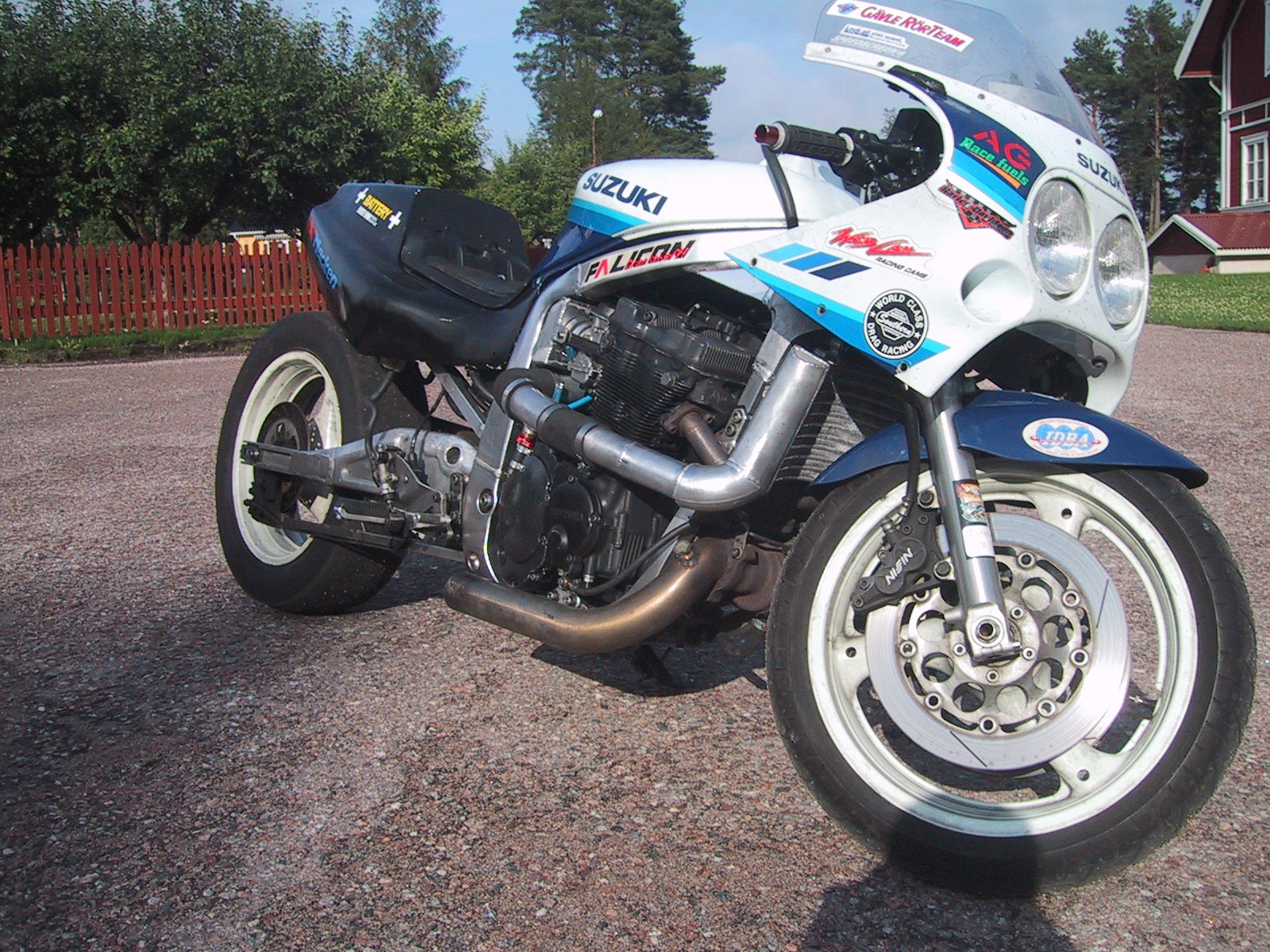
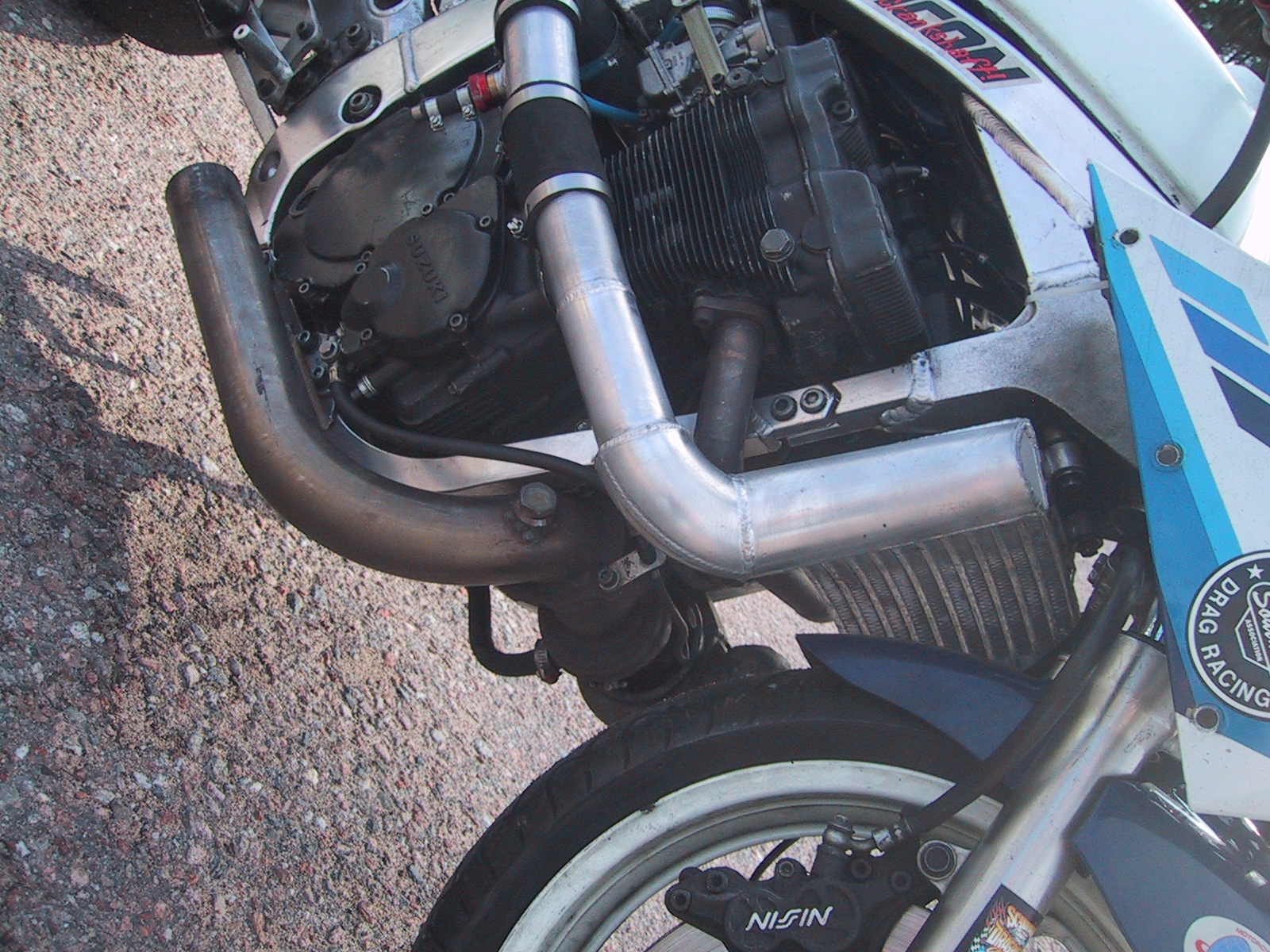
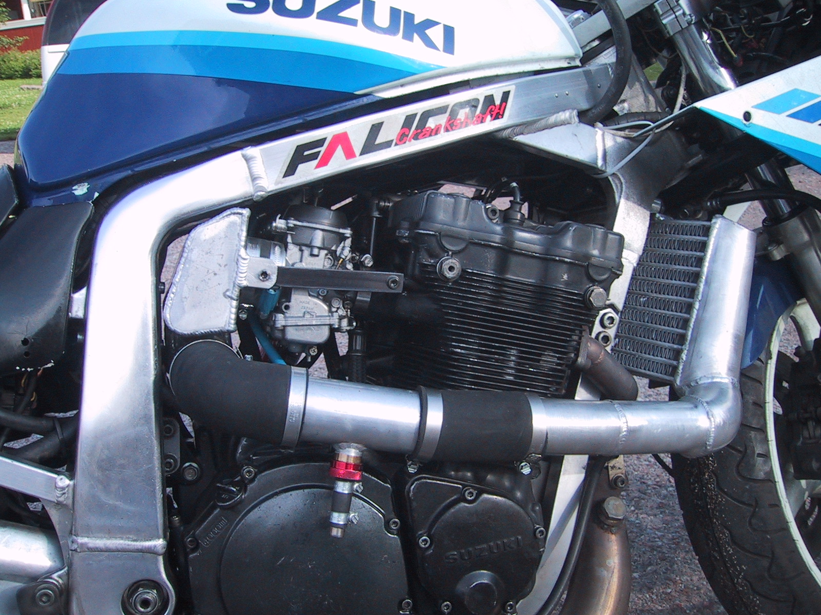
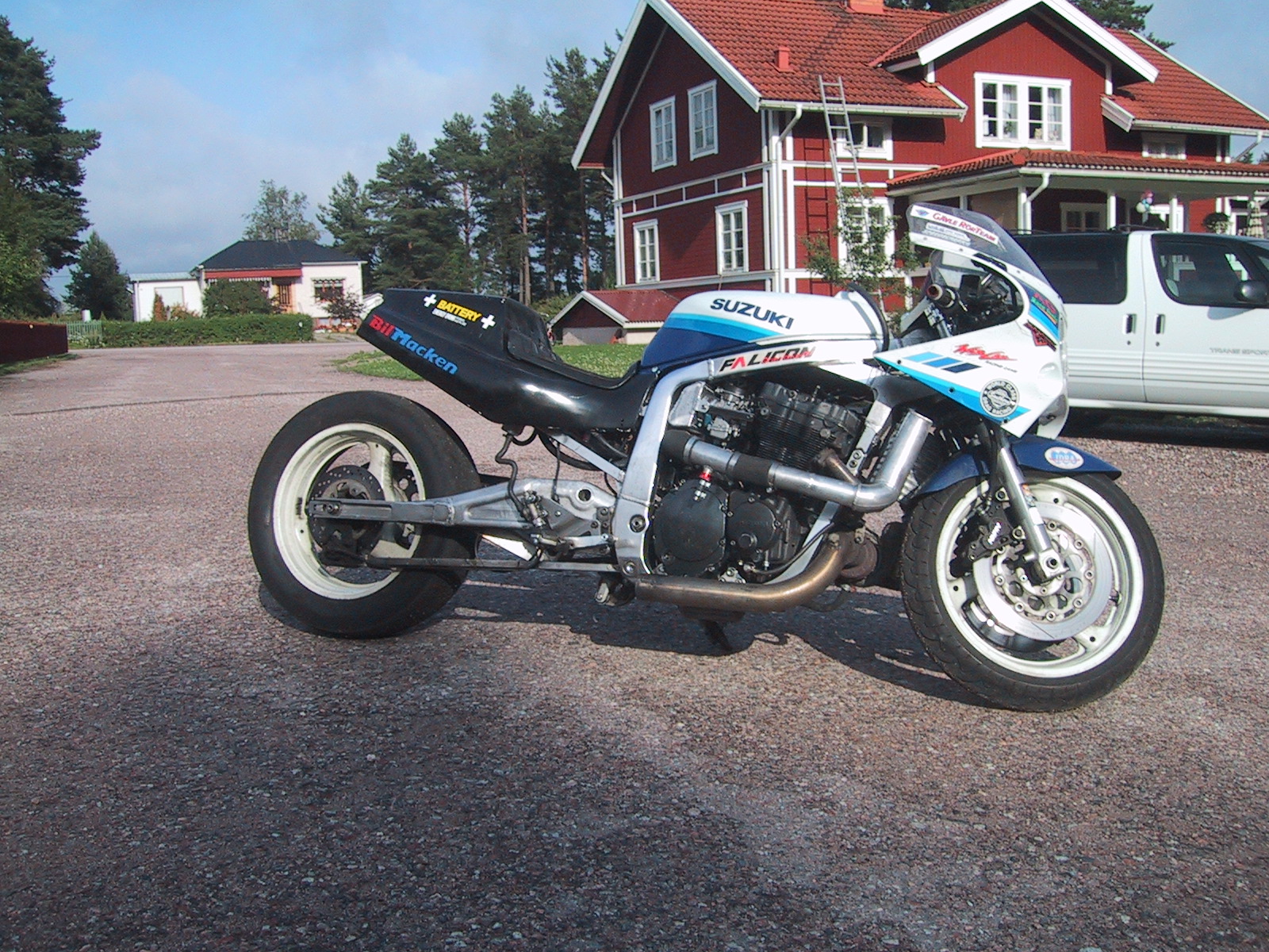
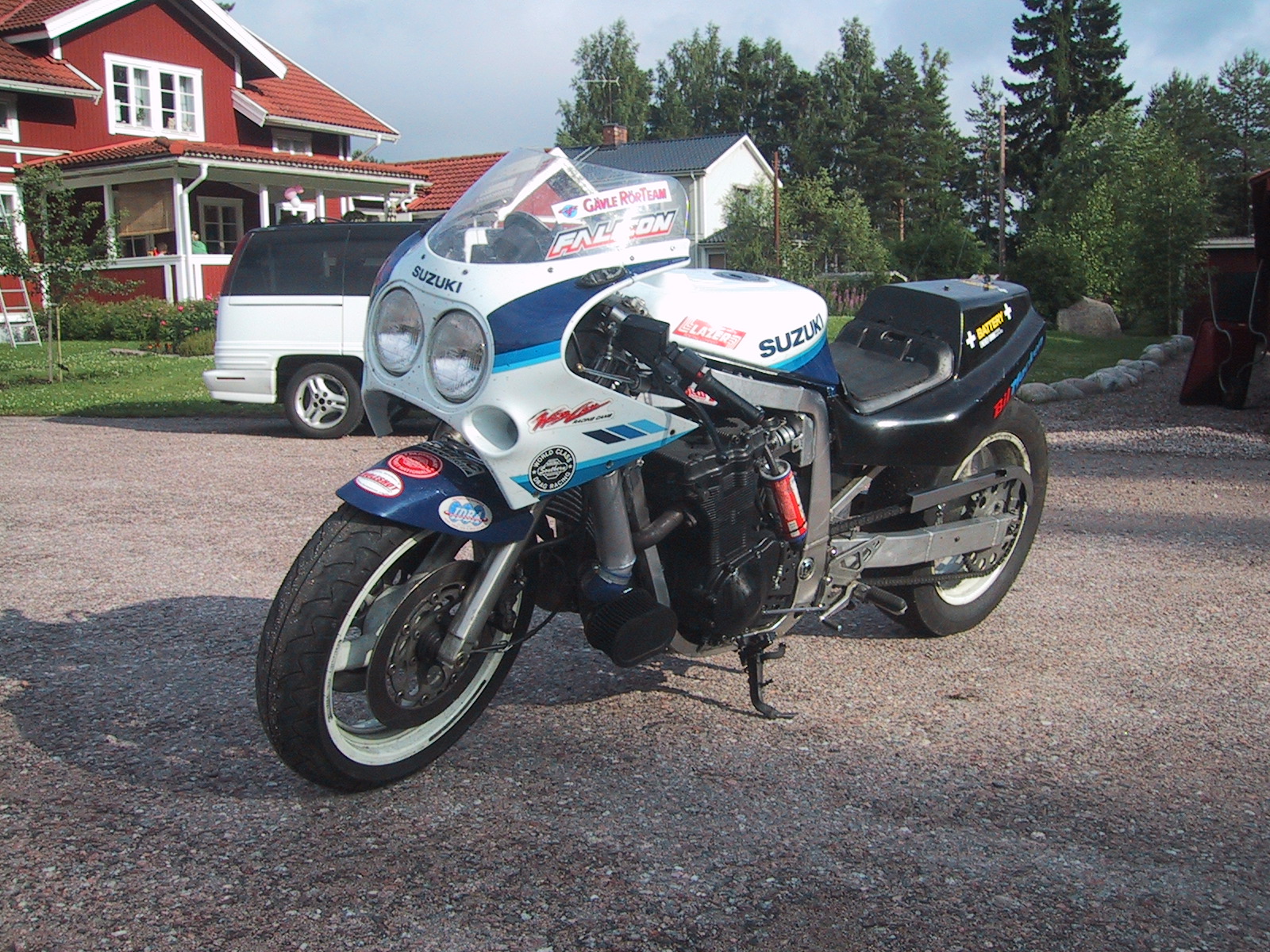
2004-07-11: My newly built turbo gixxer. Bandit 79 mm pistons, 0.5 mm
spacer, TD04-16T,
home made intercooler. http://ncracing.com intake plenum. SAAB 9000 fuel
pump. Malpassi fuel regulator. Bailey 1" dump valve. 3" exhaust pipe. Not yet
on the dyno. It breaks loose in 3rd gear with a 7" slick.
TURBOCHARGING 101
Some tech excerpts from http://pub31.ezboard.com/fazbiketechfrm9
Credits to Gary Evans garyevans@cableaz.com
Water/alcohol injection
Water injection rate, starting at a pre-set boost (pressure switch) when you think it's wise to start fighting detonation, should be about 20% of the total fuel consumption at full throttle (could be 10% to 25% depending on your application).
12 lbs. of boost on pump gas is danger zone using stock (high compression) internals and water injection.
For a 20% water mix on a 300 rwhp bike you need to supply 275 cc/min (26 lbs./hr).
Check the flow rate by pressurizing the water tank with regulated compressed air (desired boost level) and measure the water consumption over 60 seconds.
Using methanol you could/should go even richer than using water, anything from 30 to 40 percent. This will give you a slight increase in power output too but also a safety feature because the intake mixture wouldn’t be able to freeze any of the plumbing in the intake plenum or carbs.
Injecting water in front of the turbo, before the compressor, is safe. A Mr. Turbo kits suck fuel through the turbo so I guess plain water should be quite safe.
Pressurize the water tank with boost from the intake plenum. That way you will have an automatic increase in the water flow rate during boost. Make sure to install a stainless steel check valve (one direction valve) so that the water stays in the water tank when the bike is shut off. I guess you could find such device in a wind shield washer system on a car.
Oil scavenging
DELTROL FLUID PRODUCTS, Bellwood ILL, Part #1001-44, is a 7 PSI check valve that is used on the oil inlet. HOKE, part #6231 F4’s special order 1 PSI cracking pressure used on the turbo oil outlet (drain) side.
Fuel pressure regulator modification
To keep the fuel pressure regulator from seing a negative pressure (vacuum) on a blow-through setup, install a check valve on the air (boost) hose to the regulator. This is the most common cause for poor idle and slightly off idle performance.
Boost control on a single port wastegate actuator can be accomplished simply by altering the pressure signal sent to the wastegate actuator. It can be done two different ways. Single stage systems can be designed using a single pressure regulator.
Multiple stage systems can be designed using individual solenoid valves with bleed vents for each desired boost level. Two stage (high/low) systems can be controlled with a single dash mounted switch but a multi-stage system is best controlled with a gear position control system.
The following schematic explains the basic designs and the parts required. All of the parts are available from MSC Industrial Supply.
http://www.mscdirect.com/aboutmsc/welcome.shtml
A = Adjustable Pressure Relief Valve #78705431, Page 3633, $15.08
This is a zero to 100 psi valve. For low boost settings a zero to 10 psi spring is needed. It is available from the valve manufacture (Norgren) through MSC as part #2069 and cost a couple of dollars. This part allows you to set the boost pressure at which the actuator begins to receive pressure thereby delaying the gate opening.
B = 1/8 NPT Check Valve #6733090, Page 3622, $6.61
This part provides venting of pressure from the wastegate in non-boost conditions.
C = Adjustable Air Regulator #04290417, Page 3600, $24.40
This part allows you to set the pressure sent to the wastegate.
D = Adjustable Flow Control Valve #80184047, Page 3624, $14.32
This part allows you to reduce the volume of air so the solenoid bleed valves can control the wastegate. Without this the volume of air may be so large that the wastegate will open even if the solenoid bleed valves are open.
E = 12V Solenoid Valve #36911840, Page 4287, $23.07
The part opens when needed to vent pressure from the wastegate actuator.
F = Adjustable Muffler Speed Control #09806050, Page 3620, $4.58
This part is used to adjust the amount of air being vented to obtain the desired boost level.
Virginia learns Turbocharging 103 - Turbines
Daddy, I've been thinking about turbines for days and realize that I know nothing about them. Please Daddy please! Ok Virginia you understand compressors, which are where the real work gets done, but the turbine is the motor that drives the compressor fan.
The turbine has a fan wheel similar to the compressor but its function is quite different. The turbine fans job is to turn the compressor by the use of exhaust gases. The turbine housings job is to control the speed of these gases as they are directed on the fan. As the exhaust gases go through the turbine housing they take a circular path only because it allows a smaller turbocharger than if it were accomplished in a straight line. The velocity of the gases is controlled by what is called the housing A/R (area ratio).
The A/R is simply a way of specifying the reduction of area that occurs in the internal tract of the housing. You can visualize this tract as a cone with the big end at the header flange and the small end at the fan end of the passage. Since the gases are under pressure (positive displacement from the engine) restricting the discharge to the fan will not slow the gases but will increase their velocity. By controlling gas velocity you can adjust when and how fast the compressor will accelerate and produce boost.
That sounds simple Daddy why not just make the gases go as fast as possible so boost will be produced at low RPM? Well Virginia it's not quite that simply. Selecting the best A/R for a particular application is a balancing act between good low and high-speed operation. The smaller the A/R the faster boost will be built at low speeds but it also will increase the gas pressure in the header at high RPM which will reduce HP. If on the other hand the A/R is too large the building of boost will be slow and may not ever reach the desired level. There is a turbine design available that can adjust A/R automatically as RPM changes but it is currently only suitable for low boost on small engines and really isn't a good candidate yet for high horsepower.
How do you know which housing A/R to use Daddy?
That’s a good question Virginia and the answer is "with some difficulty". You either start with an educated guess based upon past knowledge or recommendations and go from there. Unless you are very certain that you know exactly which A/R will work best it makes sense to select a turbocharger that has various size housing readily available. Usually but not always, they are interchangeable with the same exterior dimensions.
Ok Daddy now I understand compressors and turbines. What else is there to know?
Well Virginia there is the subject of center bearing sections and wastage’s but that for another time. Night, night now!
Virginia learns Turbocharging 102 - Turbo Compressors
Daddy, I can't sleep. Can we talk turbocharging again?
Sure Virginia, where did we leave off last time? You were talking about compressor maps Daddy but I'm not sure why. Well I started with compressor maps since it is always best to understand where you're going before you start engineering a turbocharger. This time we'll talk about sizing the turbocharger compressor and next time we can cover the turbine side.
OK Daddy please go through this step-by-step so I can follow.
Of course Virginia take a look at this spreadsheet and I'll walk you through it.
We will fill in the columns in from left to right.
1) Target boost levels are entered in this case starting at 8 lbs and going up to 30 lbs.
2) Adjusted PSI is atmospheric pressure (14.7) in this case adjusted for Phoenix Arizona. You subtract .5 PSI for every 1000 ft of altitude.
3) Pressure ratio is calculated by "boost pressure" plus "Adjusted atmospheric pressure" divided by ""Adjusted atmospheric pressure".
4) Cubic inches of displacement (CID) in this case for a 1300 cc engine.
5) Maximum RPM to be used.
6) Density ratio is the way that compressor efficiency is taken into account and you use the chart shown to determine density based upon pressure ratio. I used an assumed efficiency of 65%.
7) Cubic feet per minute (CFM) is the volume of air that the compressor will have to support for each boost level. It is calculated by ".5" times "CID" times "RPM" divided by "1728" times ".95" (volumetric efficiency) times "density ratio".
8) Lbs/min and square meters/min are just two other ways to express CFM since some compressor maps utilize these units.
9) Est'd rear wheel HP is just a ballpark estimate from CFM.
That’s all of the spreadsheet work required. Lets assume our maximum boost level will be 20 lbs. The spreadsheet tells us that the compressor must be capable of flowing at least 412 CFM. Some manufactures list their compressor by CFM so this can help narrow down the choices.
Now lets go back to the compressor map that I picked for an example.
The 3 plots on the map represent 10, 15 and 20 Lbs of boost. Is this map a good fit? It's not bad since 10 - 20 lbs of boost falls within the 70% efficiency range of the compressor. This compressor could actually support 25 lbs if needed. Ideally all necessary plots would fall right into the center of the highest efficiency range but compromises are often necessary.
That Virginia is the engineering process by which you will pick a compressor for the car (or bike) you will someday own. Now off to bed!
Virginia learns Turbocharging 101 - Compressor maps
Daddy, when I grow up I want a turbo on my car too.
That's nice Virginia all good girls should have one.
Daddy, can we play make believe like I needed one now?
Of course Virginia but then you will need to go to bed.
OK daddy, now how will I know which turbocharger to buy?
Well Virginia there are two possible good methods and one bad. The first good one is to copy what someone else has done successfully and the second is to go through the engineering steps yourself to determine exactly what you need. The bad approach would be to ask someone else who only knows what they read on the Internet.
Daddy lets not ask anyone else lets engineer one.
OK Virginia, there are two basic parts to engineer. The first is the compressor section and second is the turbine. Lets start with the compressor. Compressor capabilities are expressed in compressor maps. Here look at this one as an example.
The compressor is rated by its ability to efficiently move a specified volume of compressed air. The higher the compressor efficiency the less the air will be heated by compression.
The vertical scale is pressure ratio, which means the total absolute pressure produced by the compressor divided by atmospheric pressure. The horizontal scale is airflow in this case measured as pounds per minute. The elliptical zones represent ranges of efficiency, which in this case range from 65 to 74%. The dotted line labeled "surge limit" represents an area that cannot be crossed because to do so would result in erratic operation and possible damage to the compressor fan. The labels on the right side of the efficiency zone are shaft RPM. In selecting a compressor you first need to determine exactly what power curve results you're after, calculate flow requirements to obtain same and plot them on the map to see if the compressor would be a good choice. The three circles represent just such a plot that we will talk about in the next chapter but right now it's your bedtime.
Thanks daddy, good night!
Formulas:
Equation for a 4-stroke: AIRFLOW = 0.5 x Engine Size x RPM x % V/Efficiency
Illustrations:
Resources:
Water injection @ http://www.aquamist.co.uk/rescr/rescr.html
Valves and fittings @ http://www.mscdirect.com/aboutmsc/welcome.shtml
Turbocharging BBS @ http://pub31.ezboard.com/fazbiketechfrm9